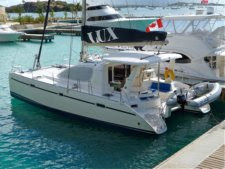
During our investigation, we heard from multiple sources that 10 years is the maximum life for standing rigging, particularly on boats that have been in charter, as LUX was. LUX is a 2005 model year Leopard 40, launched Nov 2004. That means that we're now at 11 years. There wasn't anything that looked suspicious and we go up the mast about every 6-12 months and take a close look at everything.
Hmmm. It's been almost 11 years, charter service, and 1x19 wire instead of 1x19 Dyform wire. It's time to get new standing rigging. This consists of a pair of inner diamonds, two outer diamonds, two cap shrouds, two lower shrouds, and the forestay. We still had several major decision points in the process of getting new standing rigging.
Question 1: Do we do the work or do we hire a rigger?
We contacted two riggers in Annapolis and received verbal quotes of around $7,000. Both suggested that we'd have to replace the roller furler, so count on another $3,500. The last boat I did this with went from an estimate of $5,000 to a bill of over $10,000. The five co-owners talked among ourselves - do we buy the parts and use mechanical fittings (e.g., Sta-Lok) to make up the rig ourselves? We decided against it - use a professional rigger to make swaged fittings, except for the forestay, which will require a mechanical fitting at the top. Companion Leopard owner Troy Bethel, who has a lot of experience with rigging, recommended Dennis Schryver to build the rigging for us. The installation process is simple.
Question 2: Do we do it in place or take the mast down?
We could save some money by doing it in place. Troy noted to us that there is risk of a tool becoming embedded in the deck when working aloft. :-( One of the other Leopard 40 owners did his one piece of rigging at a time, taking it to a rigger to make the replacement, then going aloft to fit it in place. This requires a number of trips aloft. However, the Moorings service bulletin recommended upgrading one of the diamonds from 6mm 1x19 to 7mm 1x19 wire. We were going to have to replace the backing plates for the larger size wire and that job is *much* easier on the ground. We had also purchased a Raymarine HD Color radome to go with our new a75 MultiFunction Display chart plotter and it needed to be mounted on the mast. So we decided to take the mast down.
Question 3: What size wire?
Note: The maintenance bulletins say that Moorings sent new wire for the inner diamonds but that since the mast has 6mm lollypop backing plates, they had fixed the rigging to fit those backing plates. Looking carefully, we found that 6mm lollypop end fittings had been welded to the threaded stud that connects to the turnbuckle. I don't know any welders whose work I would trust that much.
Removing the Mast

Before we went to the marina, we removed the sails and boom, which we stored on the foredeck. We tied a tape measure to the spinnaker halyard and ran it up to the spinnaker block, which swivels. We took measurements to the two bow D-rings and to the toe rail outboard of the Waste deck fittings. Stbd rail at waste: 51' 8-7/8", Port rail at waste: 51' 9", Stbd D-ring: 54' 2-3/4", Port D-ring: 54' 2-1/2". The mast was centered left-to-right on the boat and we had fore-aft position measurements.
 |
| Marking the wiring inside |
 |
| Wind Instrument Wiring |
 |
| Feedthrough at the foot of the mast |
We also removed the electrical connections inside the mast step, marking them with hashes to indicate which wire went where on the terminal block. The two bottom pairs of wires are ground so their order on the bottom two terminal block screws does not matter. The wind instrument wires are color coded.
It was easier to unscrew the drip fitting outside than to try to slide the wires out. We later discovered that the fitting was filled with clear silicon caulk, so the wires are effectively glued in place.
So down came the mast when we hauled for bottom painting and saildrive maintenance.
 |
| Removing the Mast |
Rigging Measurements
Troy pointed us to Dennis Schryver at Bay Sailing Equipment in Fall River, MA (owned by Frank Colaneri). He was easy to work with and we had clear communications throughout the process. We measured the old rigging, going pin-to-pin or to the middle of the lollypop fittings, using a 100ft metal tape measure. Troy recommended shortening the measurements by 1/2 inch, to allow for stretch. (Note: The diamonds were sized just right with the shorter measurements. The shrouds were a little shorter than I'd like, with 4 threads showing, but we've only just put up the rig and we should see it stretch over time. Curious about the stretch characteristics, I checked the stretch of Dyform wire at
http://www.secosouth.com/mm5/pdf_for_web/1-marine_rigging_introduction.pdf. Sure enough, at 1000kg, it stretches about 1/2 inch over the length of the shrouds. Now, do we expect a 1000kg load? I didn't run any numbers, but I'll bet that the shock loads of a poorly controlled jibe are at least that much. Maybe a mechanical engineer can leave a comment about the anticipated loads. The measurements were compiled into a
measurement document and sent to Dennis. We made sure that the turnbuckles had been marked prior to removing the rig and repositioned them to make the measurements. Each wire was clearly labeled. We also measured the pin diameters and the holes that the pins fit into. (You
do have a set of calipers on board, don't you?) Everything was checked multiple times by more than one person.
 |
| Lollypop measurement 24' 5" |
 |
| Pin measurement 29' 1-1/4", Stbd Lower Shroud |
 |
| Measuring a Pin |
 |
| Measuring a Chainplate Hole |
 |
| Furler set screws |
The furler came right apart, with the exception of two screws, one on one of the sections and another where the lowest foil section goes into the furler drum assembly. So we left them alone. The roller furler bearings (upper and lower) were good - smoothly rotating, so we don't need to rebuild them. We didn't need a new furler. Each furler section was labeled with tape so we could reassemble it in the original order.
Preparing for New Rigging
We couldn't find the lollypop threaded stud fittings that were used on the original diamonds, so we decided to move the turnbuckles up the wires about 3 feet. Dennis said that he needs that much length to keep the wire from turning into a bird's nest when cutting and swaging it.
 |
| Old 6mm Lollypop Backing Plate |
 |
| Sizing Up the New Backing Plate |
We had to replace the 6mm lollypop backing plates in the mast with 8mm versions, which Dennis obtained for us. The old backing plates were held in with monel rivets, which we drilled out with a 1/4-inch drill. We made wooden plugs that fit into the old holes left by the 6mm backing plates and tapped them into the holes with a hammer. A piece of mylar was created to align with the single hole of the 6mm backing plate and show us the location of the center of the 8mm backing plate hole and its two new screw holes. A short time with a sharp hole saw (1-5/8), then drill two 1/4 inch holes and we had new backing plate mounting holes. We cleaned up the hole edges with a round file.
A 1/4-inch drive socket fits into the opening of the 8mm backing plate. So we used a couple of 1/4-inch extensions and bolted the backing plates in place, covering the backing plate's mounting surface with Duralac to prevent dis-similar metal corrosion. The screws were coated with Tefgel, also for dis-similar metal protection, before inserting them and screwing into the nylock nuts held by the socket. These backing plates could be mounted with rivets, but we had problems finding monel rivets without a steel mandrel. Aluminum rivets aren't strong enough for this purpose.
 |
| Mylar Drilling Template |
 |
| The Hole Saw Plug |
 |
| Drilling the New Hole |
 |
| Finished 8mm Backing Plate |
While the mast was down, we took the opportunity to do a couple of other things. The foot of the mast was removed and the screws cleaned (one was broken and it was replaced). We ran new pull cords in both mast conduits, tied to short wire tails at the top of the mast so that UV doesn't destroy the nylon cord. We replaced the anchor light, which had a cracked lens. We didn't replace the VHF antenna and cable, which we hope we don't regret. It has been operating well and shows a good SWR when connected to the VHF radio. The mast contains two conduits, shown here with the foot of the mast removed. One conduit was empty, which we used for the Radar and PA speaker cables.
 |
| Two Conduits |
 |
| Masthead with Wire Tails on Pull Strings |
 |
| Mast Internals |
Radar
We added radar to LUX and decided to go with a Kato Marine radome mount, which looks real nice. It is boat show season and every new boat that was being assembled had one. They are $540. We mounted it just above the spreaders, using mylar separators to keep the stainless mount from contacting the aluminum mast. Tefgel was used on the screws. The 10 meter cable from Raymarine reaches this point with about 2 feet of cable inside. A second 10 meter cable extends from this point to the helm, where it connects to power and to the Raymarine a75 MFD. The radar comes with this second cable - the extension cable must be used to go up the mast. We cut a 1-inch hole in the mast, aligned with the conduit that runs the length of the mast on the starboard side. It is empty on LUX, so we didn't have to worry about cutting any wires when drilling. A short session with a file rounded the edge. We were barely able to work the end of the radar cable into the conduit with this size hole. A PA speaker was added to the radome mount and a wire was run for it. After both wires were in place, we used a 11/16 ID grommet with a 1-inch diameter by 3/16 groove to finish the edge of the hole and prevent the wires from chaffing. A pair of wire ties prevent the wires from sliding down the conduit. The final installation looks very good.
 |
| Radome Mount |
 |
| Final Radome Mount |
 |
| Radar & PA Cables |
 |
| Rigging Arrived! |
The Rigging Arrives! Assembly Starts
The rigging arrived and we checked its measurements. The turnbuckles had to be unscrewed to reach the measured lengths and everything looks good. The diamonds were positioned on the mast and we began tensioning them, working back and forth between the four turnbuckles, doing no more than two turns each. We checked the mast for straightness (port to starboard) and prebend (fore and aft) as the prebend approached our target number of 7-7/8 inches. We had to experiment with which turnbuckles to adjust to keep the mast straight. After the mast prebend was set, we let it sit a night and found that nothing had changed the next morning. So we pinned the turnbuckles with cotter pins.
 |
| Turnbuckle Location on Inner Diamonds |
 |
| It Looks Straight |
The roller furler was reassembled on the forestay using medium thread locker on the set screws. The overall length was double checked. The mark Dennis left for us was exactly what we had specified. We used a cutoff wheel in a drill to cut the forestay cleanly. The Sta-lok mechanical fitting worked smoothly. We took a few minutes to watch a YouTube video on assembling it. Some LifeSeal caulk was used during the final assembly to keep salt moisture out of the fitting. Dennis made us a new pin and toggle for the bottom of the forestay. There is a temptation to reuse some components, but this should be resisted. We replaced everything, including all the pins. The spreader boot is by Isomat and fits better than the old leather boot. It's much smoother too. We used silicon tape (e.g., Rescue Tape) to tape it in place.
 |
| Furler Joint Marked |
 |
| Reassembled Joint with LocTite |
 |
| Cutting the Forestay |
 |
| Sta-Lok Ready for Assembly |
 |
| New Spreader Boot |
We were finally ready, brought LUX back to the boat yard, and stepped the mast. Unfortunately, we had the lower shrouds mounted on the wrong side of the diamonds, so the yard crew shimmied up the mast and fixed them for us. We pinned the rigging in place and tightened the turnbuckles hand-tight and took LUX home. The next day we spent more time to tension the rig, mount the boom and add the sails. We're now waiting for some wind to go sailing to do final adjustments. The forestay should sag about 6 inches in 15-20 kn of breeze (3-4 inches in 10-15). After that sail, we'll insert the cotter pins in these turnbuckles and wait a few months to check the rig again.

 Before we went to the marina, we removed the sails and boom, which we stored on the foredeck. We tied a tape measure to the spinnaker halyard and ran it up to the spinnaker block, which swivels. We took measurements to the two bow D-rings and to the toe rail outboard of the Waste deck fittings. Stbd rail at waste: 51' 8-7/8", Port rail at waste: 51' 9", Stbd D-ring: 54' 2-3/4", Port D-ring: 54' 2-1/2". The mast was centered left-to-right on the boat and we had fore-aft position measurements.


