Sunday, January 18, 2015

Thru-Hull Replacement

Holding Tank Drain with Signs of Leakage
One of the most important items on our summer refit list was replacing the thru-hulls that we had not already replaced. LUX has four thru-hulls below the water line in the hulls, plus one built into each saildrive in the engine compartments. The port hull water intake had been replaced a year ago, increasing its size from 3/4 inch to 1.5 inch. It feeds a Groco manifold that supplies raw water to the toilet, air conditioner, and genset. We really wanted to replace the holding tank gravity drain fittings, which were showing signs of leakage. Other Leopard owners had reported decay of their thru-hulls, making us nervous.

Thru-Hull After Removing the Mushroom Head

One of the thru-hulls showed signs of decay through about 1/2 the thickness of the metal.


We had been planning to install a backing plate on the inside of the thru-hulls to strengthen the hull, however, we found that the hull in the area of the holding tank drains is 1-7/32 inch thick. There's plenty of strength there with a solid layup.
Holding Tank Drain Hull Thickness

Toilet Water Intake Hull Thickness


The bottom of the hull where the toilet water intake is located was much thinner, about 1/4 inch thick. A G10 board backing plate was used for that thru-hull.

One of our concerns was that the thru-hull fitting was NPS (National Pipe Straight), which doesn't thread more than a few threads into a NPT (National Pipe Tapered) fitting. We took care of this by running an NPT tap over the end of the thru-hull fitting, giving it a tapered thread. The resulting tapered thread seated nicely in the full depth of the NPT bronze elbow.


Final Installation
  -Terry

Refrigeration System Ducting

We've always wondered about the efficiency of the Sea Frost condenser and compressor system. It is in the same compartment as the port hot water heater. The engine cooling water loop runs from the bulkhead to the hot water heater, adding its heat to the compartment. To try to gain a little more efficiency out of the existing unit, we took two measures.

Water Heater Loop Hose with Insulation
The first was to insulate the engine cooling water hoses and re-route them to reduce their length. The 7/8 inch ID pipe insulation from Home Depot fits the hoses perfectly. We used some thin mylar and aluminum ducting tape (not the fabric duct tape) to help hold the insulation hose closed. It is best to wrap a piece of tape around the hose every six inches.

The next observation is that the compartment gets warm from the heat expelled through the insulation on the hoses, from the hot water heater, and from the fuel tank when we're running the engines for very long. So we created a small duct to go over the condenser intake and ran the cooling air supply duct to this duct. It is constructed from a piece of 3/8 inch thick foam insulation and is held onto the side of the Sea Frost with velcro. A 4-inch mounting ring connects to the air supply hose.
Sea Frost Cooling Air Duct

  -Terry


Fuel Tank Corrosion - Again

Fuel tank corrosion is a repeat topic on the Yahoo Leopard List. Some people have converted to plastic tanks. Others have stayed with aluminum. There isn't a great answer because both have had problems.

In our post Its Not Over Til Its Over - Port Engine Fuel Tank, we described what we thought was the last of the fuel tank problems. Well, we returned to Annapolis this summer (2014) and found another leak in the port fuel tank. We removed the starboard tank and check it. In both cases, we found salt under the tanks. The port tank had a leak along one of the seams and on the bottom of the sump that's built into the tank. We had cleaned up the water around the port tank before. If we can eliminate the salt water intrusion, we will eliminate the source of corrosion.

It took us two trips to the welder to get the port tank fixed. They had tested it after welding by putting about 6-10 lb of pressure in it and looking for the reading to change. But the weld was leaking. They also couldn't find it by spraying it with diluted dishwashing liquid. However, if it was checked with industrial leak detector, which makes industrial-strength bubbles, the leak was seen. Neither of us was happy about the second trip. We had suspected the original weld because it wasn't shiny all the way around. But they said it was good. We'll know better in the future when we see work that we don't trust and do something to double check it.

Water Stains at Hot Water Bulkhead Feed-Thru
We found a lot of orange staining around the engine cooling water loop that goes to the hot water heater where it comes through the bulkhead. Sure enough, the balsa core was wet when we removed the feed-thru fitting. We cleaned out the rotten balsa, filled with thickened epoxy, and bedded the fitting with butyl tape.


We also added drain holes to the low spots on the shelf that holds the fuel tank and the hot water tank. All holes were sealed with thickened epoxy. We'll be checking periodically to see if salt water is finding its way under the tanks.

Drain Holes Under Hot Water Heater

Drain Holes Under Fuel Tank


  -Terry

Epoxy or Polyester Resin?


We prefer epoxy because it forms both an adhesive and a mechanical bond to the polyester resin used in the original construction. Our understanding is that polyester repairs primarily result in a mechanical bond and that chemical bonding is weaker than that achieved by epoxy. See West System epoxy for fiberglass boat repair; epoxy vs polyester.  http://www.westsystem.com/ss/assets/Uploads/Ew22Fiberglass.pdf

Gougeon Brothers (West Epoxy) has also done experiments on applying polyester gelcoat over epoxy, with good results, as reported in their paper Polyester over gelcoat.

  -Terry

Rudder Post Bearing and Seal

Water has been getting into the engine compartments ever since we bought LUX. Last year we sealed the aft rail and the hull-to-deck seam. Much to our surprise and disappointment, we still had water coming in. The leak causes the engine compartment bilge pump to run about every 30 minutes. We've become accustomed to it, but would prefer that it only came on when there was a problem. So we needed to stop the water ingress.

Rudder Post and Thrust Bearing Before Grease
We identified the source as the rudder tube. LUX has the 40HP Volvo MD2040 engines, which weigh more than the Yanmar engines found on later models. This causes her to sit slightly stern-down in the water. When under way at 7kn, the stern is even lower. The water level is above the top of the rudder post tube and some of it leaks into the engine compartment. The lip seal at the top of the bearing was obviously not working well. There was some speculation that the rudder post was moving enough laterally to wear out the seal.

The rudder thrust bearing shows a lot of rusty color and we can see a steady flow of water when we're under way.  Ed Koplin on Esprit de Mar, had recommended filling the rudder post tube with grease as a way to avoid water ingress and to lubricate the lower rudder bearing. We decided that it was worth a try.


We obtained some stainless grease fittings from our local Ace Hardware. These fittings have a short threaded stud. We drilled and tapped a hole in the upper part of the rudder post for them - one per post and positioned so that it was easy to hold a grease gun on the fitting. We made two blocks to help support the rudder thrust bearing from the pressure of the grease, just as Ed did. Ken Pimentel, who was visiting us in Annapolis at the time, installed grease fittings without the aluminum blocks and it seems to be working fine for him. Everything was assembled with Tef Gel, to prevent corrosion between the stainless and aluminum components.
Upper Rudder Post Bearing

Upper Rudder Post Bearing Being Inserted


We also removed the upper rudder post bearings, cut out the balsa core, filled with thickened epoxy, and rebedded the bearing housings. Note that each bearing slips into and out of its fitting by turning it on its side. We added grease to the bearing so that it would more easily align with the rudder shaft and would provide some lubrication between the bearing and the shaft.
Final Rudder Post Grease Assembly
Sealed the Rudder Post Upper Bearing Holes

The rudder post thrust bearing was cleaned up and greased. The thrust bearing collar was installed and grease was pumped into the rudder tube until grease came out of the top. The final assembly is shown in this photo.

We've never experienced a lot of friction in the helm action, so the grease didn't change the amount of force that we need to use on the helm. But it has eliminated the source of water in the engine compartment. We now have dry engine compartments and when the bilge light comes on, we know to go investigate.


  -Terry

Summer Stop-the-Leaks Refit Project

The old phrase "You can never be too thin or too rich." shouldn't apply to the deck under load-bearing fittings. For example, I was curious about the best place to attach a cruising spinnaker's tack. The answer back was to use the D-rings located on the bows. I was originally a little hesitant because the fiberglass looked a bit thin. I didn't know how thin.

We did a summer refit on LUX, addressing a number of projects, including fixing the small leaks from the hardware of the bow-mounted D-rings that are used to attach the snatch blocks that we use for the spinnaker tack lines. The D-rings came off easily; no problem there. Just be careful to not drop the small rubber piece that keeps the ring from vibrating against the hull. However, we were surprised at the resulting fiberglass thickness--about 3/8 inch! We also noticed that there were some gelcoat cracks on deck around the fittings. We don't recall those being there when we purchased LUX. Inspection of the aft D-rings showed similar cracking of the gelcoat. Removing those fittings showed even more cracks and thin fiberglass. A significant amount of the thickness of the deck at the aft fittings was the layer of gelcoat. The resulting fiberglass was only about 1/4 inch thick! No wonder it was cracking!
Cracking around D-Ring Aft
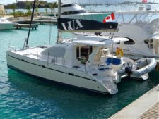
Cracking around D-Ring at Bow

English Wheel
We had some 1/8 inch thick aluminum plate left from making fuel tank inspection plates, so we cut pieces for the bow and stern. The bow plates were cut as trapezoids 6 inches long, 2.5 inches wide at the forward end and 4 inches wide at the aft end. Next problem: how can we get the plates properly shaped to fit into the tight curve of the bow? Well, we don't have an English Wheel.


Shaping the Bow D-Ring Backing Plate
But we do have a ball peen hammer, vice grips, and a tree stump handy. Just grab the aluminum plate with the vice grips and start hammering. We started hammering a line down the middle and expanded to either side. Sure enough the plate started to take shape. Four trips between the stump and LUX resulted in a good fit.
We cleaned up the inside of the hull with a rotary tool and a sanding drum, cut two layers of fiberglass mat and epoxied the mat and plate into place inside the hull. Thickened epoxy was used to help fill the gaps between the hull and the mat and the plate, providing a good distribution of load to the hull. The plate was pressed into place with a stick, forcing excess epoxy out and making sure that the plate was well supported.

The deck cracks were repaired with new gelcoat. (We've still not determined the mix of colors used in the off-white deck gelcoat.) The D-rings and screws were cleaned up on a wire wheel. It turns out that the metric screws had to be replaced with longer screws, which we were able to obtain from Fawcett's in Annapolis.

The D-rings were reinstalled using butyl tape as described by Compass Marine. http://www.pbase.com/mainecruising/rebedding_hardware

We had to bed the bow D-rings twice because we didn't use enough butyl tape the first time. The hull curves under the D-rings, which makes sealing them a challenge. One of the bow D-rings needed the gelcoat sanded a bit to provide a flat surface against which the D-ring would properly seal.

Starboard Aft D-Ring Backing Plate
We used the same process on the aft D-rings, making differently shaped backing plates and cutting a little of the old fiberglass around the fitting to allow the backing plate to fit. Some shaping of these backing plates was also needed to adapt to the curve of the balsa core in the decking. (We had to remove the head liner in the aft cabins to perform this work.)

Cabin Top Hardware

While doing the D-ring work, we had a nice rain storm come through and we found some more water dripping from the headliner in the main salon. When we removed the headliner, we found that it had been leaking for quite some time. It looks like most of the time the headliner absorbed the dripping water and no leak was apparent. Over time, the water started to rot the headliner plywood. We used Git-Rot epoxy to seal and stiffen the damaged headliner plywood.

Water Stains on Plywood Headliner
The water was coming from the hard-top support struts where they bolted to the salon deck. The struts have backing plates, which we thought was a good idea. We removed the struts and found that the holes through the hard-top had also been leaking, so we removed the wet balsa and dried out the holes with a small computer fan that's powered from a 12v wall wart. It takes about 24 hours to completely dry. Note the wood blocks that supported the hard-top while the repairs are being done. When the holes were dry, we filled them with epoxy thickened with colloidal silica.

Computer Fan and Power Brick for Drying Balsa Core


Hard-top Strut Backing Plate
The backing plate for the port hard-top strut didn't sit flat, relative to the bolts, adding strain to the setup. We cut a piece of oak flooring to fit under the backing plate so that it would sit square to the bolts.

We also noted water stains from some of the turning blocks on deck, so they came off too. Our set of balsa removal tools received a workout on all the deck holes and hard-top holes. One of the tools is made from a coat hanger. The other two are made from steel wire. The round handle on the thicker tool is easier on the hand than the T-handle on the medium tool. The end of each wire is shaped into a chisel wedge by hammering it on the anvil section of our big bench vise at home, then sharpening it with a file. 

Another tool is made by cutting off the head of a nail, bend the end 90 degrees, hammer the end flat, and sharpen it with a file. Chuck it in a drill and spin it around in the bolt hole to cut out the balsa. We have several of these tools with different length cutting arms.

Balsa Extraction Tools


Port Cabin Top Turning Block Backing Plate
Some of the turning blocks only had fender washers and nuts holding them in place. No wonder they started leaking! So we made and shaped backing plates for them too. This plate is on the turning block that's above the electrical panels on the port side of the salon.


There is a whole series of blocks on the starboard cabin top to lead the lines into the set of line clutches and the winches at the helm. We created one big backing plate for all three stacks of blocks. The other backing plate in this photo is for the starboard hard-top strut. We didn't find much wrong with the backing used for the line clutches and they weren't leaking, so we left them alone. We added another clutch for the spinnaker sheet from the port side. 

Starboard Cabin Top Backing Plates


All cabin top and hard-top holes were filled with thickened epoxy.


Toe Rail Leaks

Another storm or two later and we identified leaks along the outside of both hulls in the forward cabins. These took a while longer to diagnose. We rebedded the bow pulpit railings on both sides with butyl tape. That helped, but wasn't the only source of water.  To simulate a rain, we directed a hose set to light spray onto the toe rail. This allowed us to localize the spray and help identify the leak. This time it was the toe rail bolts. We could see corrosion on some of the bolts and nuts. Those were good candidates for replacement. We used butyl tape for them too, wrapping it around the beveled head and the upper body of the bolt before inserting it into the toe rail. This took care of the port side leaks, but the starboard side still leaked. The boat is built by setting the deck on top of the hulls and bolting through the overlap. The overlap is similar to asphalt shingles on a house roof. A low-grade caulk is used for the hull-to-deck joint and sometimes this caulk doesn't extend as far as it should to prevent leaks. The toe rail seems to direct some water back into the overlap, where it eventually finds an opening. Most of the time the opening is back outside, but sometimes it is through a screw hole.

Carbon Screws Holding Hull-to-Deck Joint
The hull-to-deck joint looks like it is held in place by carbon steel screws, which have since rusted. We see them ever few inches along the joint. A better caulk (3M 5200 or 4200) with stainless screws would have been much better and not much more expensive. Of course, when the screws rust, they expand, adding a separating force to the joint.

How do we fix the problem with water ingress along the hull-to-deck joint? We're adverse to filling the space with regular epoxy due to its low elongation characteristics. However, we note that in several areas, such as the lockers and the V-berth, the seam has been covered with fiberglass. We decided to use the G/flex epoxy to fill some of the spaces and that seems to have solved the problem. In some cases, we had to drill out the toe rail bolt hole, fill it with G/flex epoxy, and re-drill in order to create a seal between the aluminum toe rail and the hull-to-deck joint. A better solution is to rebed the entire toe rail, but that's more work (i.e. time) than we could afford this summer.

Hatches and Line Deflectors

Of course, we also had leaks from two hatches, so they had to get rebedded. It seems that someone in the past decided to rebed the hatches with either 3M 4200 or 5200. After persistent attack with thin putty knives, we were able to break the bond between the hatch and the deck. It required going around the inside of the hatch from inside the cabin as well as working along the deck outside. We found that the bolts around the hinge area are particularly susceptible to leaking. We rebedded them with butyl caulk.

The rope guard around the starboard forward hatch looked like it had been rebedded, but with a very thin layer of poor quality caulk. It leaked a lot! We had only seen a little of the water, because it primarily dripped on the back of the headliner, which directed the flow to other areas as well as absorbing some of the water. Only when we removed the Ocean Air screen assembly did we see the full volume of water ingress. These were really easy to rebed with butyl caulk.

The final leaks that we found this summer were around the helm. There are two hand railings outboard of the helm seat and both needed to be rebedded. We could see staining on the head liner plywood and on the nut + washer. So they were unbolted, cleaned, and rebedded.

The result of our work was a drier boat. The bilges have remained dry through several hard rainstorms this winter.


  -Terry

Saturday, January 17, 2015

The LUX ICW Bridge Log

One of the reasons for selecting the Leopard 40 was that it was one of the largest catamarans that we could find that would fit under the ICW bridges. The specifications list the mast as 61ft 11in above DWL. LUX tends to sit bow-high in the water, so the actual mast height above the water with our typical load is a few inches more. As we use water, the height increases an inch or two.

We performed two measurements on LUX to determine the overall height, which includes the metal whip VHF antenna. Both measurements came in at 64ft 10in. The whip antenna is like the Shakespeare Classic 5242-A, which is 3 ft long. That correlates with the masthead at 62ft.

We read about the variations in bridge height on the ICW and decided that the best way to approach the trip was "carefully." When we approach a bridge, we make sure there is no other boat traffic (sometimes a challenge) and slow to a dead crawl (slow enough to react if the bridge is too low for us to pass, which we can tell by the wind instrument that's out front). We call it the "Bridge Dance." Having two engines to allow slewing the boat to adjust for wind and current is really nice. There is a big challenge when there is a strong current running with us and we have to use a significant amount of reverse power to counter the current.

Another idea that we've toyed with is running a GoPro up the mast on a boat hook, rigged as a gin pole on the Spinnaker halyard, to get it above the mast. With the wifi capability, we'd get to see the oncoming bridge on our iPad.

We have logged the bridge passages from Annapolis, MD to Ft. Pierce, FL. We are mostly successful in recording the following items:

* Bridge height board readings (when there are boards showing).
* The state of the tide and sometimes the height of the water on the bridge, based on past high water marks on the bridge fender boards.
* An estimate of how much we cleared or touched a bridge.

We keep the log in an Excel spreadsheet. It is provided below as a Google Sheets format so that you can download it and keep all the formatting. (There doesn't seem to be a way to upload a .xls file and make it available for download.) Any log entries where we have touched a bridge are noted in red. The log includes all bridges, even those that open, simply because they were in the original listing that we found online. The original listing shows the charted height of each bridge. We ignore that now and instead pay attention to the log entries we've made and the current state of the tide (or the wind if we're inshore where wind is the primary force that changes water height).


You are welcome to download and use it, but like any good mariner, you're responsible for your own actions in using anything in it. In other words, we're not responsible for your use of it. If you select all rows+columns, copy it, then paste into a spreadsheet, it will retain the formatting.

LUX Published ICW Bridge Log (updated 12/02/2019)

You can also use a GoPro camera on a pole to check the bridge clearance before attempting to transit a span that looks close. See our other post Verifying Bridge Heights.

  -Terry